#ConfigBytes
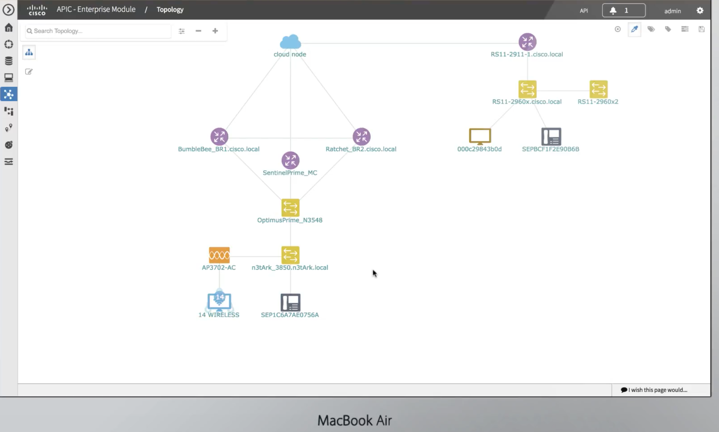
APIC-EM Overview and Demonstration
Video Format #ConfigBytes
NXOS: OSPF Auto-Cost Reference Bandwidth
Intent:
By default, the auto-cost reference bandwidth is set to 40Gbps on NXOS. This makes my 40G interface have a cost of 1.
40,000,000,000(Reference BW in bps) / 40,000,000,000(interface BW in bps) = 1
My intention is to make the cost of 40Gbps = 2, 10G = 10, and 100 = 1
Default Cost Calculation
cybertron-2(config-router)# sh ip ospf
Routing Process CCIE with ID 2.2.2.2 VRF default
Routing Process Instance Number 1
Stateful High Availability enabled
Graceful-restart is configured
Grace period: 90 state: Inactive
Last graceful restart exit status: None
Supports only single TOS(TOS0) routes
Supports opaque LSA
Administrative distance 110
Reference Bandwidth is 40000 Mbps
cybertron-2(config-router)# sh ip ospf int brief
OSPF Process ID CCIE VRF default
Total number of interface: 4
Interface ID Area Cost State Neighbors Status
Lo0 1 0.0.0.0 1 LOOPBACK 0 up
Lo1 3 0.0.0.0 1 LOOPBACK 0 up
Eth1/1 2 0.0.0.0 4 P2P 1 up < 10Gbps Interface
Eth1/51 4 0.0.0.0 1 BDR 1 up < 40Gbps Interface
Time to configure an auto-cost reference bandwidth
router ospf CCIE
router-id 2.2.2.2
auto-cost reference-bandwidth 100000
Now let’s look back at the interface cost again.
cybertron-2(config-router)# sh ip ospf int brief
OSPF Process ID CCIE VRF default
Total number of interface: 4
Interface ID Area Cost State Neighbors Status
Lo0 1 0.0.0.0 1 LOOPBACK 0 up
Lo1 3 0.0.0.0 1 LOOPBACK 0 up
Eth1/1 2 0.0.0.0 10 P2P 1 up
Eth1/51 4 0.0.0.0 2 BDR 1 up
Finally, some math to go along with that.
100,000,000,000 (configured reference bandwidth) / 40,000,000,000 (40G interface BW) = 2.5
100,000,000,000 (configured reference bandwidth) / 10,000,000,000 (10G interface BW) = 10
Observation:
NXOS seems to round DOWN cost, instead of up. In our example 2.5 is rounded down to 2.
NXOS: Private VLANs
Intent:
Make ports e100/1/5-6 Isolated (NO communications between secondary VLAN members) and ports e100/1/9-10 Community ports (communications ALLOWED between secondary VLAN members)
feature private-vlan
vlan 200
private-vlan primary
private-vlan association 201-202
vlan 201
private-vlan isolated
vlan 202
private-vlan community
interface Vlan200
Promiscuous_SVI
no shutdown
private-vlan mapping 201-202
ip address 10.1.1.254/24
Starscream-1# sh vlan private-vlan
Primary Secondary Type Ports
——- ——— ————— ——————————————-
200 201 isolated Eth100/1/5, Eth100/1/6
200 202 community Eth100/1/9, Eth100/1/10
interface Ethernet100/1/5
switchport mode private-vlan host
spanning-tree port type edge
switchport private-vlan host-association 200 201
interface Ethernet100/1/6
switchport mode private-vlan host
spanning-tree port type edge
switchport private-vlan host-association 200 201
interface Ethernet100/1/9
switchport mode private-vlan host
switchport access vlan 100
spanning-tree port type edge
switchport private-vlan host-association 200 202
interface Ethernet100/1/10
switchport mode private-vlan host
switchport access vlan 100
spanning-tree port type edge
switchport private-vlan host-association 200 202
IOS: PVLANs
Intent:
The private-VLAN feature addresses two problems that service providers face when using VLANs:
•Scalability: The switch supports up to 1005 active VLANs. If a service provider assigns one VLAN per customer, this limits the numbers of customers that the service provider can support.
•To enable IP routing, each VLAN is assigned a subnet address space or a block of addresses, which can waste the unused IP addresses and cause IP address management problems.
Using private VLANs addresses the scalability problem and provides IP address management benefits for service providers and Layer 2 security for customers.
Private VLANs partition a regular VLAN domain into subdomains and can have multiple VLAN pairs—one for each subdomain. A subdomain is represented by a primary VLAN and a secondary VLAN.
All VLAN pairs in a private VLAN share the same primary VLAN. The secondary VLAN ID differentiates one subdomain from another.
Terminology:
•Isolated VLANs—Ports within an isolated VLAN cannot communicate with each other at the Layer 2 level.
•Community VLANs—Ports within a community VLAN can communicate with each other but cannot communicate with ports in other communities at the Layer 2 level.
•Promiscuous—A promiscuous port belongs to the primary VLAN and can communicate with all interfaces, including the community and isolated host ports that belong to the secondary VLANs associated with the primary VLAN.
•Isolated—An isolated port is a host port that belongs to an isolated secondary VLAN. It has complete Layer 2 separation from other ports within the same private VLAN, except for the promiscuous ports. Private VLANs block all traffic to isolated ports except traffic from promiscuous ports. Traffic received from an isolated port is forwarded only to promiscuous ports.
•Community—A community port is a host port that belongs to a community secondary VLAN. Community ports communicate with other ports in the same community VLAN and with promiscuous ports. These interfaces are isolated at Layer 2 from all other interfaces in other communities and from isolated ports within their private VLAN.
Deep Dive:
Primary and secondary VLANs have these characteristics:
•Primary VLAN—A private VLAN has only one primary VLAN. Every port in a private VLAN is a member of the primary VLAN. The primary VLAN carries unidirectional traffic downstream from the promiscuous ports to the (isolated and community) host ports and to other promiscuous ports.
•Isolated VLAN —A private VLAN has only one isolated VLAN. An isolated VLAN is a secondary VLAN that carries unidirectional traffic upstream from the hosts toward the promiscuous ports and the gateway.
•Community VLAN—A community VLAN is a secondary VLAN that carries upstream traffic from the community ports to the promiscuous port gateways and to other host ports in the same community. You can configure multiple community VLANs in a private VLAN.
Link to Cisco.com documentation for more details and configuration examples.
Use Cases: Shared environments (think service providers multi tenet buildings), conservation of IP space, and breaking the broadcast domain into multiple isolated sub-broadcast domains.
Configuration Example: (SW1 & SW2, SW1 fa0/1 is promiscuous, fa0/13 on both sides is the 802.1q trunk)
#1 Rule: PVLANs only work with VTP transparent mode!!! I believe VTPv3 support PVLANs but, I have not confirmed this.
SW1:
sw1#sh vlan private-vlan

Primary Secondary Type              Ports
------- --------- ----------------- ------------------------------------------
100     1000      community         Fa0/1, Fa0/3
100     2000      community         Fa0/1, Fa0/5
100     3000      isolated          Fa0/1
"VTP MODE TRANSPARENT"
vlan 100
  private-vlan primary
  private-vlan association 1000,2000,3000
vlan 1000
  private-vlan community
vlan 2000
  private-vlan community
vlan 3000
  private-vlan isolated
sw1#sh run int fa 0/1
!
interface FastEthernet0/1
 switchport private-vlan mapping 100 1000,2000,3000
 switchport mode private-vlan promiscuous

sw1#sh run int fa 0/3
!
interface FastEthernet0/3
 switchport private-vlan host-association 100 1000
 switchport mode private-vlan host

sw1#sh run int fa 0/5
!
interface FastEthernet0/5
 switchport private-vlan host-association 100 2000
 switchport mode private-vlan host
!
sw1#sh run int fa 0/13
!
interface FastEthernet0/13
 switchport trunk encapsulation dot1q
 switchport mode trunk
SW2:
sw2#sh vlan private-vlan
Primary Secondary Type              Ports
------- --------- ----------------- ------------------------------------------
100     1000      community         Fa0/2
100     2000      community         Fa0/4
100     3000      isolated          Fa0/6
"VTP MODE TRANSPARENT"
vlan 100
  private-vlan primary
  private-vlan association 1000,2000,3000
vlan 1000
  private-vlan community
vlan 2000
  private-vlan community
vlan 3000
  private-vlan isolated
sw2#sh run int fa 0/2
!
interface FastEthernet0/2
 switchport private-vlan host-association 100 1000
 switchport mode private-vlan host
end

sw2#sh run int fa 0/4
!
interface FastEthernet0/4
 switchport private-vlan host-association 100 2000
 switchport mode private-vlan host

sw2#sh run int fa 0/6
!
interface FastEthernet0/6
 switchport private-vlan host-association 100 3000
 switchport mode private-vlan host
!
interface FastEthernet0/13
switchport trunk encapsulation dot1
switchport mode trunk
Now let’s say that the promiscuous port is an SVI (routed VLAN interface). There is an extra step to take so that you don’t get burned (trust me I did and it sucked).
SW2:
interface vlan 100
ip address 10.0.0.1 255.255.255.0
private-vlan mapping 1000,2000,3000 (the isolated VLAN (3000) should only be mapped to SW2)
Verify isolation with a ping to 255.255.255.255 from each router/host.
Disclaimer: The opinions expressed in this blog are my own views and not those of Cisco

